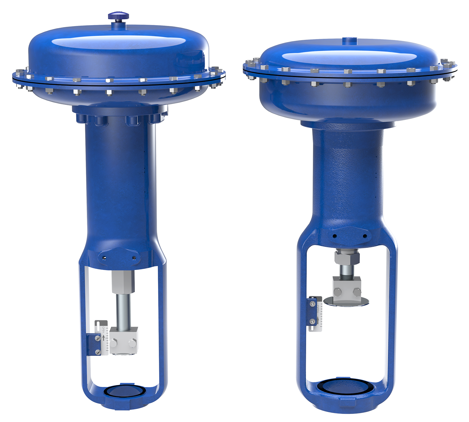
DFC & DFO Linear Spring & Diaphragm Actuators
previous
next

DFC & DFO Linear Spring & Diaphragm Actuators

  • 3-15 PSIG (0.21-1.03 BARG) or 6-30 PSIG (0.41-2.07 BARG) Input Signal
  • 3/8" (9.5mm) | 1/2" (12.7mm) | 3/4" (19.1mm) Valve Stem Compatibility
  • 2-1/8" (54mm) | 2-13/16" (71mm) |  3-9/16" (90mm) Yoke Boss Size
  • -40°F to 180°F (-40°C to 82°C) Standard Temperature Limitations
More Details

Model DFC (Fail Closed) and DFO (Fail Open) linear spring and diaphragm actuators are large diaphragm area actuators that allow for low-pressure operation. The spring provides fail safe positioning for a control valve on loss of pneumatic supply pressure. Both DFC and DFO actuators can be used to automate control valves for throttling or on/off control of liquids or gases.

Overview

DFC & DFO Linear Spring & Diaphragm Actuators

Quick Data
Models
FT35, FT45
Frame Sizes 3, 5, 8
Stroke6, 12, 18


  • Open Yoke / Open Valve Stem Design

  • Heavy Duty Protective Coatings Available

  • Handwheels and Travel Stop Options Available

  • Versatile Instrument Mounting Options

Product Specifications

DFC Actuator SpecificationsOpen arrow
DFC ACTUATOR SPECIFICATIONS
SPECIFICATIONS ACTUATOR SIZE
1046 1069 2069 2105 2156 3105 3156 3220 (1)
NOMINAL EFFECTIVE AREA INCH2 46 69 69 105 156 105 156 220
cm2 297 445 445 667 1,006 677 1,006 1,419
YOKE BOSS SIZE INCH 2-1/8 2-1/8 2-13/16 2-13/16 2-13/16 3-9/16 3-9/16 3-9/16
cm 54 54 71.5 71.5 71.5 90.5 90.5 90.5
ACCEPTABLE VALVE STEM DIAMETER INCH 3/8 3/8 1/2 1/2 1/2 3/4 3/4 3/4
mm 9.5 9.5 12.7 12.7 12.7 19.1 19.1 19.1
MAXIMUM ALLOWABLE OUTPUT THRUST lb 2,300 2,300 2,700 5,650 7,550 5,650 6,800 8,800
N 10,230 10,230 12,010 25,132 33,584 25,132 30,248 39,144
MAXIMUM TRAVEL (2) STANDARD INCH 3/4 1-1/8 1-1/2 2 2 2 2 3 (3)
mm 19.1 28.6 38.1 50.8 50.8 50.8 50.8 76.2
TOP-LOADED INCH N/A 3/4 N/A 3/4 N/A N/A 1-1/8 N/A
mm N/A 19.1 N/A 19.1 N/A N/A 28.6 N/A
MAXIMUM CASING PRESSURE FOR ACTUATOR SIZING (4,5) PSIG 55 70 70 65 55 65 55 50
BARG 380 483 483 448 379 448 379 345
MAXIMUM EXCESS DIAPHRAGM PRESSURE (4) PSIG 55 20 20 10 10 10 10 10
BARG 380 138 138 69 69 69 69 69
MAXIMUM DIAPHRAGM CASING PRESSURE (4,5) PSIG 110 90 90 75 65 75 65 60
BARG 760 621 621 517 448 517 448 414
MATERIAL TEMPERATURE CAPABILITIES NITRILE -40°F to 180°F (-40°C to 82°C)
SILICONE -40°F to 180°F (-40°C to 82°C)
NOTES: (1) These values also apply to the DFC Size 3220-4 actuator.
(2) Actuator travel may be less than the value listed after connected to the valve.
(3) Maximum actuator travel for the 3220-4 is 4 inches (102 mm).
(4) Additional pressure may be added to the actuator when the actuator is at full travel. Damage to the actuator will occur if the Maximum Excess Diaphragm Pressure is exceeded. When the actuator has reached its full travel, and the diaphragm plate is physically stopped from moving, the energy from additional pressure is transferred to the diaphragm and casing. The amount of excess pressure that can be added at full travel is limited, exceeding this limiting factor will result in damage to the actuator, leakage, and/or casing fatigue or deformation.
(5) This Maximum Casing Pressure is not to be used for normal operating pressure. Its purpose is to allow for typical regulator supply settings and/or relief valve tolerances. The maximum casing pressure is the pressure that can be applied to the actuator when the actuator is at less than full travel. Damage to the actuator may occur if this pressure is exceeded before the full travel is reached.
DFO Actuator SpecificationsOpen arrow
DFO ACTUATOR SPECIFICATIONS
SPECIFICATIONS ACTUATOR SIZE
1046 1069 2069 2105 2156 3105 3156 3220 (1)
NOMINAL EFFECTIVE AREA INCH2 46 69 69 105 156 105 156 220
cm2 297 445 445 667 1,006 677 1,006 1,419
YOKE BOSS SIZE INCH 2-1/8 2-1/8 2-13/16 2-13/16 2-13/16 3-9/16 3-9/16 3-9/16
cm 54 54 71.5 71.5 71.5 90.5 90.5 90.5
ACCEPTABLE VALVE STEM DIAMETER INCH 3/8 3/8 1/2 1/2 1/2 3/4 3/4 3/4
mm 9.5 9.5 12.7 12.7 12.7 19.1 19.1 19.1
MAXIMUM ALLOWABLE OUTPUT THRUST lbf 2,300 2,300 2,700 5,650 7,550 5,650 6,800 8,800
N 10,230 10,230 12,010 25,132 33,584 25,132 30,248 39,144
MAXIMUM TRAVEL (2) INCH 3/4 1-1/8 1-1/2 2 2 2 2 3 (3)
mm 19.1 28.6 38.1 50.8 50.8 50.8 50.8 76.2
MAXIMUM CASING PRESSURE FOR ACTUATOR SIZING (4) PSIG 125 65 65 50 40 50 40 55
BARG 862 448 448 345 276 345 276 379
MAXIMUM DIAPHRAGM CASING PRESSURE (4,5) PSIG 140 75 75 60 50 60 50 65
BARG 965 517 517 414 345 414 345 448
MATERIAL TEMPERATURE CAPABILITIES NITRILE -40°F to 180°F (-40°C to 82°C)
NOTES: (1) These values also apply to the DFO Size 3220-4 actuator.
(2) Actuator travel may be less than the value listed after connected to the valve.
(3) Maximum actuator travel for the 3220-4 is 4 inches (102 mm).
(4) The Operating Diaphragm Pressure must not exceed the Maximum Diaphragm Casing Pressure and must not produce a force on the actuator stem greater than the maximum allowable valve stem load.
(5) This Maximum Casing Pressure is not to be used for normal operating pressure. Its purpose is to allow for typical regulator supply settings and/or relief valve tolerances. The maximum casing pressure is the pressure that can be applied to the actuator when the actuator is at less than full travel. Damage to the actuator may occur if this pressure is exceeded before the full travel is reached.

DFC & DFO Actuator Documentation

DFC Instruction Manual
Dynaflo, DynaFlo, Linear Actuator, Manuals & Software
DFC Operation, Parts, Maintenance and Assembly Instructions
DFC & DFO Sales Bulletin
Brochures, DynaFlo, Dynaflo
DFC/DFO Actuator Technical Specifications
DFO Instruction Manual
Dynaflo, DynaFlo, Linear Actuator, Manuals & Software
DFO Operation, Parts, Maintenance and Assembly Instructions
Refer to our FloSpec software for product selection, sizing and ordering

Refer to our FloSpec software for product selection, sizing and ordering

This site uses cookies to improve our service, you can find out more here - for the best web experience please accept cookies

x