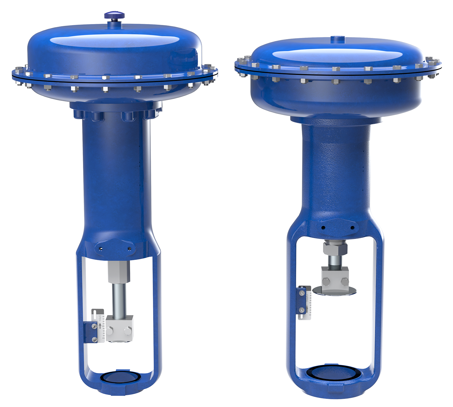
| DFC ACTUATOR SPECIFICATIONS |
| SPECIFICATIONS |
ACTUATOR SIZE |
| 1046 |
1069 |
2069 |
2105 |
2156 |
3105 |
3156 |
3220 (1) |
| NOMINAL EFFECTIVE AREA |
INCH2 |
46 |
69 |
69 |
105 |
156 |
105 |
156 |
220 |
| cm2 |
297 |
445 |
445 |
667 |
1,006 |
677 |
1,006 |
1,419 |
| YOKE BOSS SIZE |
INCH |
2-1/8 |
2-1/8 |
2-13/16 |
2-13/16 |
2-13/16 |
3-9/16 |
3-9/16 |
3-9/16 |
| cm |
54 |
54 |
71.5 |
71.5 |
71.5 |
90.5 |
90.5 |
90.5 |
| ACCEPTABLE VALVE STEM DIAMETER |
INCH |
3/8 |
3/8 |
1/2 |
1/2 |
1/2 |
3/4 |
3/4 |
3/4 |
| mm |
9.5 |
9.5 |
12.7 |
12.7 |
12.7 |
19.1 |
19.1 |
19.1 |
| MAXIMUM ALLOWABLE OUTPUT THRUST |
lb |
2,300 |
2,300 |
2,700 |
5,650 |
7,550 |
5,650 |
6,800 |
8,800 |
| N |
10,230 |
10,230 |
12,010 |
25,132 |
33,584 |
25,132 |
30,248 |
39,144 |
| MAXIMUM TRAVEL (2) |
STANDARD |
INCH |
3/4 |
1-1/8 |
1-1/2 |
2 |
2 |
2 |
2 |
3 (3) |
| mm |
19.1 |
28.6 |
38.1 |
50.8 |
50.8 |
50.8 |
50.8 |
76.2 |
| TOP-LOADED |
INCH |
N/A |
3/4 |
N/A |
3/4 |
N/A |
N/A |
1-1/8 |
N/A |
| mm |
N/A |
19.1 |
N/A |
19.1 |
N/A |
N/A |
28.6 |
N/A |
| MAXIMUM CASING PRESSURE FOR ACTUATOR SIZING (4,5) |
PSIG |
55 |
70 |
70 |
65 |
55 |
65 |
55 |
50 |
| BARG |
380 |
483 |
483 |
448 |
379 |
448 |
379 |
345 |
| MAXIMUM EXCESS DIAPHRAGM PRESSURE (4) |
PSIG |
55 |
20 |
20 |
10 |
10 |
10 |
10 |
10 |
| BARG |
380 |
138 |
138 |
69 |
69 |
69 |
69 |
69 |
| MAXIMUM DIAPHRAGM CASING PRESSURE (4,5) |
PSIG |
110 |
90 |
90 |
75 |
65 |
75 |
65 |
60 |
| BARG |
760 |
621 |
621 |
517 |
448 |
517 |
448 |
414 |
| MATERIAL TEMPERATURE CAPABILITIES |
NITRILE |
-40°F to 180°F (-40°C to 82°C) |
| SILICONE |
-40°F to 180°F (-40°C to 82°C) |
| NOTES: |
(1) |
These values also apply to the DFC Size 3220-4 actuator. |
| (2) |
Actuator travel may be less than the value listed after connected to the valve. |
| (3) |
Maximum actuator travel for the 3220-4 is 4 inches (102 mm). |
| (4) |
Additional pressure may be added to the actuator when the actuator is at full travel. Damage to the actuator will occur if the Maximum Excess Diaphragm Pressure is exceeded. When the actuator has reached its full travel, and the diaphragm plate is physically stopped from moving, the energy from additional pressure is transferred to the diaphragm and casing. The amount of excess pressure that can be added at full travel is limited, exceeding this limiting factor will result in damage to the actuator, leakage, and/or casing fatigue or deformation. |
| (5) |
This Maximum Casing Pressure is not to be used for normal operating pressure. Its purpose is to allow for typical regulator supply settings and/or relief valve tolerances. The maximum casing pressure is the pressure that can be applied to the actuator when the actuator is at less than full travel. Damage to the actuator may occur if this pressure is exceeded before the full travel is reached. |


